
It has a wide range of variants with uncompromising performance.
Due to the low contact force, the working support can be used as a supporting surface for workpieces or additional clamping arms and accessories.
They are indispensable when processing complex irregular workpieces.

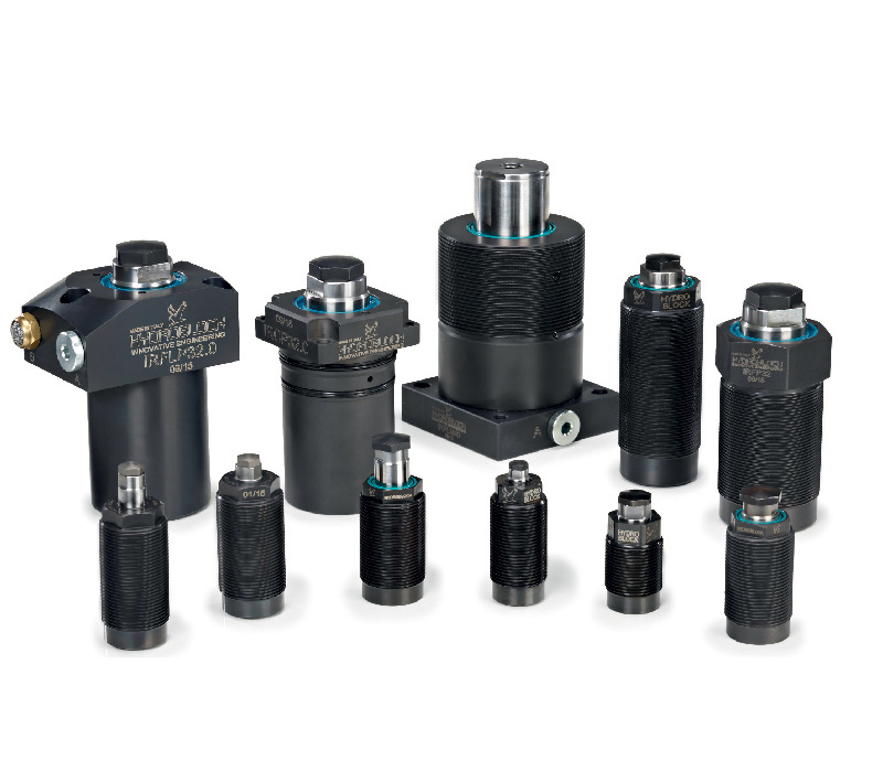

Product List

Threaded type M22x1.5
Available versions:
Version with hydraulic method
Normal extension (spring proximity)
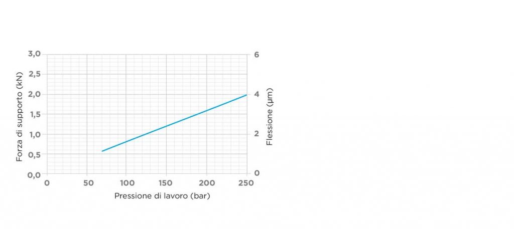
Total cylinder stroke (mm) 4.5
Maximum working pressure (Bar) 250
Supporting force at 200 Bar (KN) 1.6
Force/Pressure/Deformation Diagram


Threaded type M26x1.5
Available versions:
Version with hydraulic method
Normal extension (spring proximity)
Piston rod diameter (mm) 16
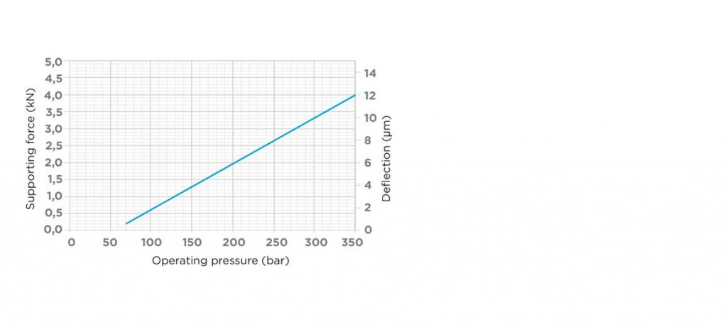
Total cylinder stroke (mm) 6.5
Maximum working pressure (Bar) 350
Supporting force at 200 Bar (KN) 2
Force/Pressure/Deformation Diagram

Threaded type M30x1.5
Available versions:
Version with hydraulic method
Normal extension (spring proximity)
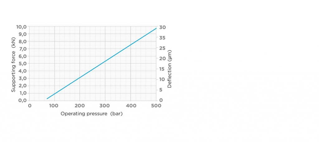
Total cylinder stroke (mm) 8
Maximum working pressure (Bar) 500
Supporting force at 200 Bar (KN) 3
Force/Pressure/Deformation Diagram

Threaded type M30x1.5
Available versions:
Version with hydraulic method
Normal extension (spring proximity)
Rod diameter (mm) 16
Total cylinder stroke (mm) 9.7
Maximum working pressure (Bar) 500
Supporting force at 200 Bar (KN) 1.8
Force/Pressure/Deformation Diagram
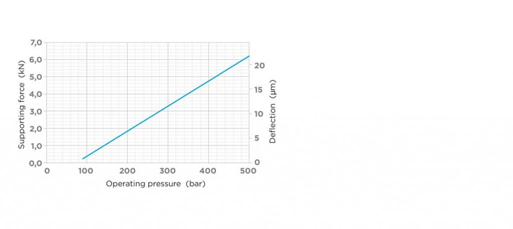

Threaded type M42x1.5
Available versions:
Version with hydraulic method
Normal extension (spring proximity)
Total cylinder stroke (mm) 8
Maximum working pressure (Bar) 500
Supporting force at 200 Bar (KN) 5.9
Force/Pressure/Deformation Diagram
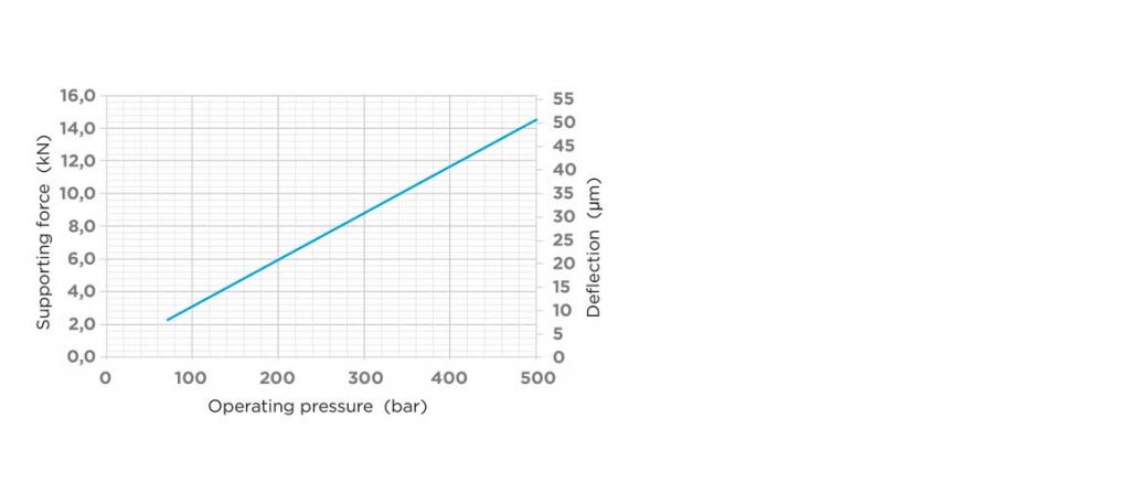

Threaded type M42x1.5
Available versions:
Version with hydraulic method
Normal extension (spring proximity)
Total cylinder stroke (mm) 13
Maximum working pressure (Bar) 500
Supporting force at 200 Bar (KN) 10.5
Force/Pressure/Deformation Diagram


Threaded type (M50x1.5), plug-in type, upper flange
Available versions:
Version with hydraulic method
Normal extension (spring proximity)
Metal wiper (optional)
Total cylinder stroke (mm) 12
Maximum working pressure (Bar) 500
Supporting force at 200 Bar (KN) 13.5
Force/Pressure/Deformation Diagram
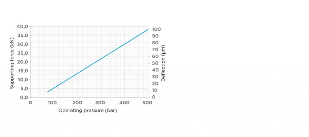

Available version:
Version with hydraulic method
Normal extension (spring approach)
Total cylinder stroke (mm) 18
Maximum working pressure (Bar) 500
Supporting force at 200 Bar (KN) 14.5
Force/Pressure/Deformation Diagram


Threaded type M30x1.5
Available versions:
Version with hydraulic method
Normal extension (spring proximity)
Total cylinder stroke (mm) 10
Maximum working pressure (Bar) 500
Supporting force at 200 Bar (KN) 1.8
Force/Pressure/Deformation Diagram
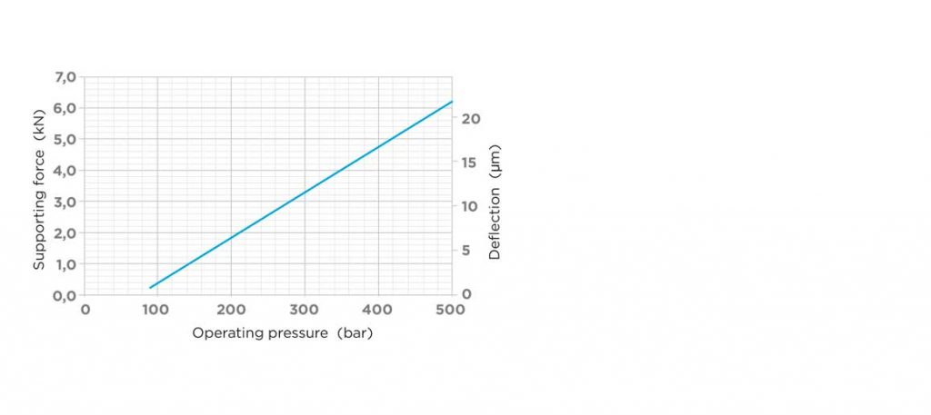
Threaded type M22x1.5
Available versions:
Version with hydraulic method
Normal extension (spring proximity)
Total cylinder stroke (mm) 4.5
Maximum working pressure (Bar) 250
Supporting force at 200 Bar (KN) 1.6
Force/Pressure/Deformation Diagram
Threaded type M26x1.5
Available versions:
Version with hydraulic method
Normal extension (spring proximity)
Piston rod diameter (mm) 16
Total cylinder stroke (mm) 6.5
Maximum working pressure (Bar) 350
Supporting force at 200 Bar (KN) 2
Force/Pressure/Deformation Diagram
Threaded type M30x1.5
Available versions:
Version with hydraulic method
Normal extension (spring proximity)
Total cylinder stroke (mm) 8
Maximum working pressure (Bar) 500
Supporting force at 200 Bar (KN) 3
Force/Pressure/Deformation Diagram
Threaded type M30x1.5
Available versions:
Version with hydraulic method
Normal extension (spring proximity)
Rod diameter (mm) 16
Total cylinder stroke (mm) 9.7
Maximum working pressure (Bar) 500
Supporting force at 200 Bar (KN) 1.8
Force/Pressure/Deformation Diagram
Threaded type M42x1.5
Available versions:
Version with hydraulic method
Normal extension (spring proximity)
Total cylinder stroke (mm) 8
Maximum working pressure (Bar) 500
Supporting force at 200 Bar (KN) 5.9
Force/Pressure/Deformation Diagram
Threaded type M42x1.5
Available versions:
Version with hydraulic method
Normal extension (spring proximity)
Total cylinder stroke (mm) 13
Maximum working pressure (Bar) 500
Supporting force at 200 Bar (KN) 10.5
Force/Pressure/Deformation Diagram
Threaded type (M50x1.5), plug-in type, upper flange
Available versions:
Version with hydraulic method
Normal extension (spring proximity)
Metal wiper (optional)
Total cylinder stroke (mm) 12
Maximum working pressure (Bar) 500
Supporting force at 200 Bar (KN) 13.5
Force/Pressure/Deformation Diagram
Available version:
Version with hydraulic method
Normal extension (spring approach)
Total cylinder stroke (mm) 18
Maximum working pressure (Bar) 500
Supporting force at 200 Bar (KN) 14.5
Force/Pressure/Deformation Diagram
Threaded type M30x1.5
Available versions:
Version with hydraulic method
Normal extension (spring proximity)
Total cylinder stroke (mm) 10
Maximum working pressure (Bar) 500
Supporting force at 200 Bar (KN) 1.8
Force/Pressure/Deformation Diagram
Threaded type M22x1.5
Available versions:
Version with hydraulic method
Normal extension (spring proximity)
Total cylinder stroke (mm) 4.5
Maximum working pressure (Bar) 250
Supporting force at 200 Bar (KN) 1.6
Force/Pressure/Deformation Diagram
Threaded type M26x1.5
Available versions:
Version with hydraulic method
Normal extension (spring proximity)
Piston rod diameter (mm) 16
Total cylinder stroke (mm) 6.5
Maximum working pressure (Bar) 350
Supporting force at 200 Bar (KN) 2
Force/Pressure/Deformation Diagram
Threaded type M30x1.5
Available versions:
Version with hydraulic method
Normal extension (spring proximity)
Total cylinder stroke (mm) 8
Maximum working pressure (Bar) 500
Supporting force at 200 Bar (KN) 3
Force/Pressure/Deformation Diagram
Threaded type M30x1.5
Available versions:
Version with hydraulic method
Normal extension (spring proximity)
Rod diameter (mm) 16
Total cylinder stroke (mm) 9.7
Maximum working pressure (Bar) 500
Supporting force at 200 Bar (KN) 1.8
Force/Pressure/Deformation Diagram
Threaded type M42x1.5
Available versions:
Version with hydraulic method
Normal extension (spring proximity)
Total cylinder stroke (mm) 8
Maximum working pressure (Bar) 500
Supporting force at 200 Bar (KN) 5.9
Force/Pressure/Deformation Diagram
Threaded type M42x1.5
Available versions:
Version with hydraulic method
Normal extension (spring proximity)
Total cylinder stroke (mm) 13
Maximum working pressure (Bar) 500
Supporting force at 200 Bar (KN) 10.5
Force/Pressure/Deformation Diagram
Threaded type (M50x1.5), plug-in type, upper flange
Available versions:
Version with hydraulic method
Normal extension (spring proximity)
Metal wiper (optional)
Total cylinder stroke (mm) 12
Maximum working pressure (Bar) 500
Supporting force at 200 Bar (KN) 13.5
Force/Pressure/Deformation Diagram
Available version:
Version with hydraulic method
Normal extension (spring approach)
Total cylinder stroke (mm) 18
Maximum working pressure (Bar) 500
Supporting force at 200 Bar (KN) 14.5
Force/Pressure/Deformation Diagram
Threaded type M30x1.5
Available versions:
Version with hydraulic method
Normal extension (spring proximity)
Total cylinder stroke (mm) 10
Maximum working pressure (Bar) 500
Supporting force at 200 Bar (KN) 1.8
Force/Pressure/Deformation Diagram
Threaded type M22x1.5
Available versions:
Version with hydraulic method
Normal extension (spring proximity)
Total cylinder stroke (mm) 4.5
Maximum working pressure (Bar) 250
Supporting force at 200 Bar (KN) 1.6
Force/Pressure/Deformation Diagram
Threaded type M26x1.5
Available versions:
Version with hydraulic method
Normal extension (spring proximity)
Piston rod diameter (mm) 16
Total cylinder stroke (mm) 6.5
Maximum working pressure (Bar) 350
Supporting force at 200 Bar (KN) 2
Force/Pressure/Deformation Diagram
Threaded type M30x1.5
Available versions:
Version with hydraulic method
Normal extension (spring proximity)
Total cylinder stroke (mm) 8
Maximum working pressure (Bar) 500
Supporting force at 200 Bar (KN) 3
Force/Pressure/Deformation Diagram
Threaded type M30x1.5
Available versions:
Version with hydraulic method
Normal extension (spring proximity)
Rod diameter (mm) 16
Total cylinder stroke (mm) 9.7
Maximum working pressure (Bar) 500
Supporting force at 200 Bar (KN) 1.8
Force/Pressure/Deformation Diagram
Threaded type M42x1.5
Available versions:
Version with hydraulic method
Normal extension (spring proximity)
Total cylinder stroke (mm) 8
Maximum working pressure (Bar) 500
Supporting force at 200 Bar (KN) 5.9
Force/Pressure/Deformation Diagram
Threaded type M42x1.5
Available versions:
Version with hydraulic method
Normal extension (spring proximity)
Total cylinder stroke (mm) 13
Maximum working pressure (Bar) 500
Supporting force at 200 Bar (KN) 10.5
Force/Pressure/Deformation Diagram
Threaded type (M50x1.5), plug-in type, upper flange
Available versions:
Version with hydraulic method
Normal extension (spring proximity)
Metal wiper (optional)
Total cylinder stroke (mm) 12
Maximum working pressure (Bar) 500
Supporting force at 200 Bar (KN) 13.5
Force/Pressure/Deformation Diagram
Available version:
Version with hydraulic method
Normal extension (spring approach)
Total cylinder stroke (mm) 18
Maximum working pressure (Bar) 500
Supporting force at 200 Bar (KN) 14.5
Force/Pressure/Deformation Diagram
Threaded type M30x1.5
Available versions:
Version with hydraulic method
Normal extension (spring proximity)
Total cylinder stroke (mm) 10
Maximum working pressure (Bar) 500
Supporting force at 200 Bar (KN) 1.8
Force/Pressure/Deformation Diagram
Threaded type M22x1.5
Available versions:
Version with hydraulic method
Normal extension (spring proximity)
Total cylinder stroke (mm) 4.5
Maximum working pressure (Bar) 250
Supporting force at 200 Bar (KN) 1.6
Force/Pressure/Deformation Diagram
Threaded type M26x1.5
Available versions:
Version with hydraulic method
Normal extension (spring proximity)
Piston rod diameter (mm) 16
Total cylinder stroke (mm) 6.5
Maximum working pressure (Bar) 350
Supporting force at 200 Bar (KN) 2
Force/Pressure/Deformation Diagram
Threaded type M30x1.5
Available versions:
Version with hydraulic method
Normal extension (spring proximity)
Total cylinder stroke (mm) 8
Maximum working pressure (Bar) 500
Supporting force at 200 Bar (KN) 3
Force/Pressure/Deformation Diagram
Threaded type M30x1.5
Available versions:
Version with hydraulic method
Normal extension (spring proximity)
Rod diameter (mm) 16
Total cylinder stroke (mm) 9.7
Maximum working pressure (Bar) 500
Supporting force at 200 Bar (KN) 1.8
Force/Pressure/Deformation Diagram
Threaded type M42x1.5
Available versions:
Version with hydraulic method
Normal extension (spring proximity)
Total cylinder stroke (mm) 8
Maximum working pressure (Bar) 500
Supporting force at 200 Bar (KN) 5.9
Force/Pressure/Deformation Diagram
Threaded type M42x1.5
Available versions:
Version with hydraulic method
Normal extension (spring proximity)
Total cylinder stroke (mm) 13
Maximum working pressure (Bar) 500
Supporting force at 200 Bar (KN) 10.5
Force/Pressure/Deformation Diagram
Threaded type (M50x1.5), plug-in type, upper flange
Available versions:
Version with hydraulic method
Normal extension (spring proximity)
Metal wiper (optional)
Total cylinder stroke (mm) 12
Maximum working pressure (Bar) 500
Supporting force at 200 Bar (KN) 13.5
Force/Pressure/Deformation Diagram
Available version:
Version with hydraulic method
Normal extension (spring approach)
Total cylinder stroke (mm) 18
Maximum working pressure (Bar) 500
Supporting force at 200 Bar (KN) 14.5
Force/Pressure/Deformation Diagram
Threaded type M30x1.5
Available versions:
Version with hydraulic method
Normal extension (spring proximity)
Total cylinder stroke (mm) 10
Maximum working pressure (Bar) 500
Supporting force at 200 Bar (KN) 1.8
Force/Pressure/Deformation Diagram
Threaded type M22x1.5
Available versions:
Version with hydraulic method
Normal extension (spring proximity)
Total cylinder stroke (mm) 4.5
Maximum working pressure (Bar) 250
Supporting force at 200 Bar (KN) 1.6
Force/Pressure/Deformation Diagram
Threaded type M26x1.5
Available versions:
Version with hydraulic method
Normal extension (spring proximity)
Piston rod diameter (mm) 16
Total cylinder stroke (mm) 6.5
Maximum working pressure (Bar) 350
Supporting force at 200 Bar (KN) 2
Force/Pressure/Deformation Diagram
Threaded type M30x1.5
Available versions:
Version with hydraulic method
Normal extension (spring proximity)
Total cylinder stroke (mm) 8
Maximum working pressure (Bar) 500
Supporting force at 200 Bar (KN) 3
Force/Pressure/Deformation Diagram
Threaded type M30x1.5
Available versions:
Version with hydraulic method
Normal extension (spring proximity)
Rod diameter (mm) 16
Total cylinder stroke (mm) 9.7
Maximum working pressure (Bar) 500
Supporting force at 200 Bar (KN) 1.8
Force/Pressure/Deformation Diagram
Threaded type M42x1.5
Available versions:
Version with hydraulic method
Normal extension (spring proximity)
Total cylinder stroke (mm) 8
Maximum working pressure (Bar) 500
Supporting force at 200 Bar (KN) 5.9
Force/Pressure/Deformation Diagram
Threaded type M42x1.5
Available versions:
Version with hydraulic method
Normal extension (spring proximity)
Total cylinder stroke (mm) 13
Maximum working pressure (Bar) 500
Supporting force at 200 Bar (KN) 10.5
Force/Pressure/Deformation Diagram
Threaded type (M50x1.5), plug-in type, upper flange
Available versions:
Version with hydraulic method
Normal extension (spring proximity)
Metal wiper (optional)
Total cylinder stroke (mm) 12
Maximum working pressure (Bar) 500
Supporting force at 200 Bar (KN) 13.5
Force/Pressure/Deformation Diagram
Available version:
Version with hydraulic method
Normal extension (spring approach)
Total cylinder stroke (mm) 18
Maximum working pressure (Bar) 500
Supporting force at 200 Bar (KN) 14.5
Force/Pressure/Deformation Diagram
Threaded type M30x1.5
Available versions:
Version with hydraulic method
Normal extension (spring proximity)
Total cylinder stroke (mm) 10
Maximum working pressure (Bar) 500
Supporting force at 200 Bar (KN) 1.8
Force/Pressure/Deformation Diagram
Threaded type M22x1.5
Available versions:
Version with hydraulic method
Normal extension (spring proximity)
Total cylinder stroke (mm) 4.5
Maximum working pressure (Bar) 250
Supporting force at 200 Bar (KN) 1.6
Force/Pressure/Deformation Diagram
Threaded type M26x1.5
Available versions:
Version with hydraulic method
Normal extension (spring proximity)
Piston rod diameter (mm) 16
Total cylinder stroke (mm) 6.5
Maximum working pressure (Bar) 350
Supporting force at 200 Bar (KN) 2
Force/Pressure/Deformation Diagram
Threaded type M30x1.5
Available versions:
Version with hydraulic method
Normal extension (spring proximity)
Total cylinder stroke (mm) 8
Maximum working pressure (Bar) 500
Supporting force at 200 Bar (KN) 3
Force/Pressure/Deformation Diagram
Threaded type M30x1.5
Available versions:
Version with hydraulic method
Normal extension (spring proximity)
Rod diameter (mm) 16
Total cylinder stroke (mm) 9.7
Maximum working pressure (Bar) 500
Supporting force at 200 Bar (KN) 1.8
Force/Pressure/Deformation Diagram
Threaded type M42x1.5
Available versions:
Version with hydraulic method
Normal extension (spring proximity)
Total cylinder stroke (mm) 8
Maximum working pressure (Bar) 500
Supporting force at 200 Bar (KN) 5.9
Force/Pressure/Deformation Diagram
Threaded type M42x1.5
Available versions:
Version with hydraulic method
Normal extension (spring proximity)
Total cylinder stroke (mm) 13
Maximum working pressure (Bar) 500
Supporting force at 200 Bar (KN) 10.5
Force/Pressure/Deformation Diagram
Threaded type (M50x1.5), plug-in type, upper flange
Available versions:
Version with hydraulic method
Normal extension (spring proximity)
Metal wiper (optional)
Total cylinder stroke (mm) 12
Maximum working pressure (Bar) 500
Supporting force at 200 Bar (KN) 13.5
Force/Pressure/Deformation Diagram
Available version:
Version with hydraulic method
Normal extension (spring approach)
Total cylinder stroke (mm) 18
Maximum working pressure (Bar) 500
Supporting force at 200 Bar (KN) 14.5
Force/Pressure/Deformation Diagram
Threaded type M30x1.5
Available versions:
Version with hydraulic method
Normal extension (spring proximity)
Total cylinder stroke (mm) 10
Maximum working pressure (Bar) 500
Supporting force at 200 Bar (KN) 1.8
Force/Pressure/Deformation Diagram
Threaded type M22x1.5
Available versions:
Version with hydraulic method
Normal extension (spring proximity)
Total cylinder stroke (mm) 4.5
Maximum working pressure (Bar) 250
Supporting force at 200 Bar (KN) 1.6
Force/Pressure/Deformation Diagram
Threaded type M26x1.5
Available versions:
Version with hydraulic method
Normal extension (spring proximity)
Piston rod diameter (mm) 16
Total cylinder stroke (mm) 6.5
Maximum working pressure (Bar) 350
Supporting force at 200 Bar (KN) 2
Force/Pressure/Deformation Diagram
Threaded type M30x1.5
Available versions:
Version with hydraulic method
Normal extension (spring proximity)
Total cylinder stroke (mm) 8
Maximum working pressure (Bar) 500
Supporting force at 200 Bar (KN) 3
Force/Pressure/Deformation Diagram
Threaded type M30x1.5
Available versions:
Version with hydraulic method
Normal extension (spring proximity)
Rod diameter (mm) 16
Total cylinder stroke (mm) 9.7
Maximum working pressure (Bar) 500
Supporting force at 200 Bar (KN) 1.8
Force/Pressure/Deformation Diagram
Threaded type M42x1.5
Available versions:
Version with hydraulic method
Normal extension (spring proximity)
Total cylinder stroke (mm) 8
Maximum working pressure (Bar) 500
Supporting force at 200 Bar (KN) 5.9
Force/Pressure/Deformation Diagram
Threaded type M42x1.5
Available versions:
Version with hydraulic method
Normal extension (spring proximity)
Total cylinder stroke (mm) 13
Maximum working pressure (Bar) 500
Supporting force at 200 Bar (KN) 10.5
Force/Pressure/Deformation Diagram
Threaded type (M50x1.5), plug-in type, upper flange
Available versions:
Version with hydraulic method
Normal extension (spring proximity)
Metal wiper (optional)
Total cylinder stroke (mm) 12
Maximum working pressure (Bar) 500
Supporting force at 200 Bar (KN) 13.5
Force/Pressure/Deformation Diagram
Available version:
Version with hydraulic method
Normal extension (spring approach)
Total cylinder stroke (mm) 18
Maximum working pressure (Bar) 500
Supporting force at 200 Bar (KN) 14.5
Force/Pressure/Deformation Diagram
Threaded type M30x1.5
Available versions:
Version with hydraulic method
Normal extension (spring proximity)
Total cylinder stroke (mm) 10
Maximum working pressure (Bar) 500
Supporting force at 200 Bar (KN) 1.8
Force/Pressure/Deformation Diagram
Threaded type M22x1.5
Available versions:
Version with hydraulic method
Normal extension (spring proximity)
Total cylinder stroke (mm) 4.5
Maximum working pressure (Bar) 250
Supporting force at 200 Bar (KN) 1.6
Force/Pressure/Deformation Diagram
Threaded type M26x1.5
Available versions:
Version with hydraulic method
Normal extension (spring proximity)
Piston rod diameter (mm) 16
Total cylinder stroke (mm) 6.5
Maximum working pressure (Bar) 350
Supporting force at 200 Bar (KN) 2
Force/Pressure/Deformation Diagram
Threaded type M30x1.5
Available versions:
Version with hydraulic method
Normal extension (spring proximity)
Total cylinder stroke (mm) 8
Maximum working pressure (Bar) 500
Supporting force at 200 Bar (KN) 3
Force/Pressure/Deformation Diagram
Threaded type M30x1.5
Available versions:
Version with hydraulic method
Normal extension (spring proximity)
Rod diameter (mm) 16
Total cylinder stroke (mm) 9.7
Maximum working pressure (Bar) 500
Supporting force at 200 Bar (KN) 1.8
Force/Pressure/Deformation Diagram
Threaded type M42x1.5
Available versions:
Version with hydraulic method
Normal extension (spring proximity)
Total cylinder stroke (mm) 8
Maximum working pressure (Bar) 500
Supporting force at 200 Bar (KN) 5.9
Force/Pressure/Deformation Diagram
Threaded type M42x1.5
Available versions:
Version with hydraulic method
Normal extension (spring proximity)
Total cylinder stroke (mm) 13
Maximum working pressure (Bar) 500
Supporting force at 200 Bar (KN) 10.5
Force/Pressure/Deformation Diagram
Threaded type (M50x1.5), plug-in type, upper flange
Available versions:
Version with hydraulic method
Normal extension (spring proximity)
Metal wiper (optional)
Total cylinder stroke (mm) 12
Maximum working pressure (Bar) 500
Supporting force at 200 Bar (KN) 13.5
Force/Pressure/Deformation Diagram
Available version:
Version with hydraulic method
Normal extension (spring approach)
Total cylinder stroke (mm) 18
Maximum working pressure (Bar) 500
Supporting force at 200 Bar (KN) 14.5
Force/Pressure/Deformation Diagram
Threaded type M30x1.5
Available versions:
Version with hydraulic method
Normal extension (spring proximity)
Total cylinder stroke (mm) 10
Maximum working pressure (Bar) 500
Supporting force at 200 Bar (KN) 1.8
Force/Pressure/Deformation Diagram